Advanced Waveform Utility
The processing varies, depending on how many carriers are selected and which sub-steps you select to enable or disable.
This topic covers the following:
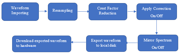
If the waveform has only one carrier and one segment, the waveform process (Figure 2) includes waveform importing, resampling, spectrum mirroring operation, crest factor reduction, waveform correction, and downloading.
Figure 2 (above) - Waveform process for one carrier and one segment
If a carrier is comprised of more than one segment, all waveform files for that carrier must be processed into the one carrier, including waveform importing, sample rate alignment, and combination in time domain (Figure 4).
The resulting waveform then has the following processes applied (Figure 5):
Further resampling
Spectrum mirroring operation
Crest factor reduction
Waveform correction and downloading
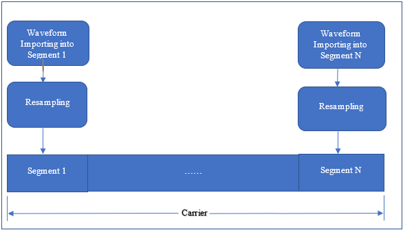
Figure 4 (above). Segments waveform combination into carrier.
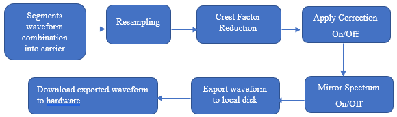
Figure 5 (above). Waveform process for one carrier and more than one segment.
If you select more than one carrier, segments waveform combination will be done first on all carriers, then all carriers will go through spectrum mirroring, frequency offset alignment, time repeating, frequency time domain combination, crest factor reduction, correction, and downloading (Figure 7).
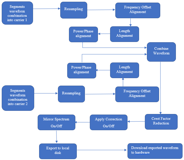
Figure 7 (above). Waveform process for two or more carriers.
The
Waveform importing from local disk
Adding/deleting/copying segments
Adding/deleting/copying carriers
Carrier sample rate and resampling ratio
IQ swapping on imported waveform
Spectrum mirroring
The settings appearing in the
If the waveform has only one carrier and one segment (Figure 8), the original sample rate of the segment is same as the carrier sample rate and the resampling ratio of carrier can be used to adjust final waveform sample rate.
Frequency offset is set here too.
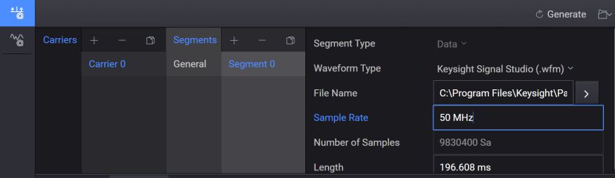
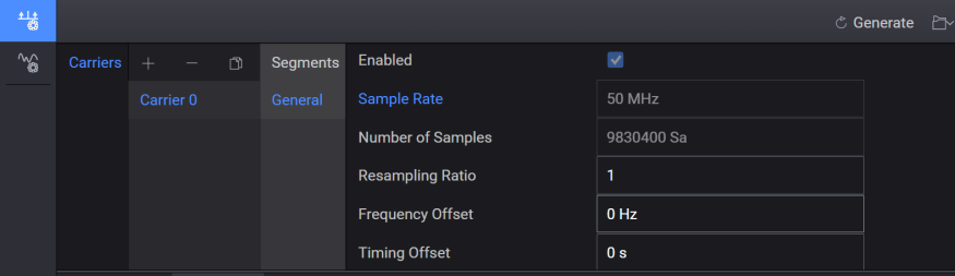
Figure 8 (above). Carrier Setup GUI for one carrier and one segment.
If the waveform has one carrier and more than one segment in the carrier, every segment can be repeatable after import before being combined into the carrier. The maximum value of sample rate of all segments will be the sample rate of final combined carrier, so all segments will be resampled to align sample rate after repeating in time domain, and resampling ratio of carrier can be used to adjust final waveform sample rate.
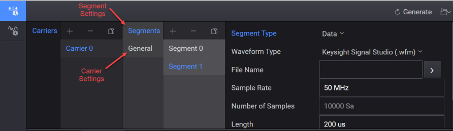
Figure 9 (above). Carrier Setup GUI for one carrier and more than one segment.
If there is more than one carrier, the segments operation is the same as described above.
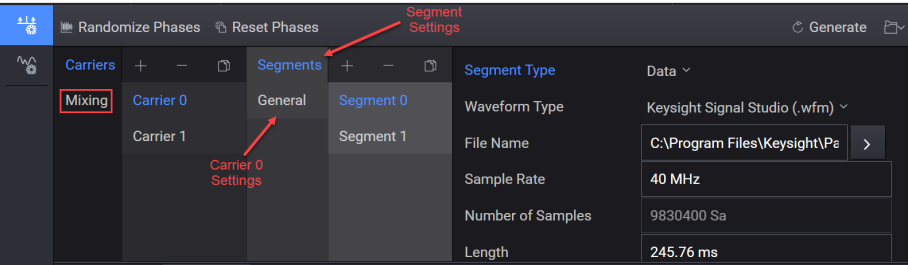
Figure 10 (above). Carrier Setup GUI for more than one carrier and more than one segment per carrier.
Used for selecting a waveform file on the GUI (Graphical User Interface). When selecting a.wfm file, the sample rate and the number of samples will be displayed in GUI. When selecting other waveform types, which have no sample rate information, only the Number of Samples is displayed and the correct sample rate should be input to playback the waveform correctly.
When using ASCII, CSV, or text files (*.dat, *.csv, *.txt), proper formatting must be applied to the IQ data of the selected waveform file. (See below.)
I1, Q1
I2, Q2
…
In, Qn
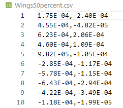
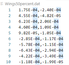
I1 Q1
I2 Q2
…
In Qn
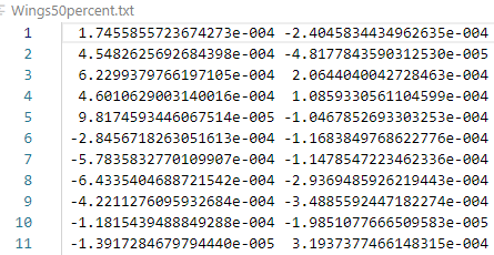
I1 Q1
I2 Q2
…
In Qn
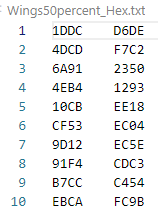
I1, Q1
I2, Q2
…
In, Qn
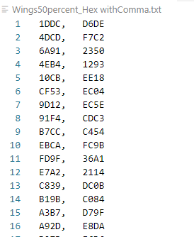
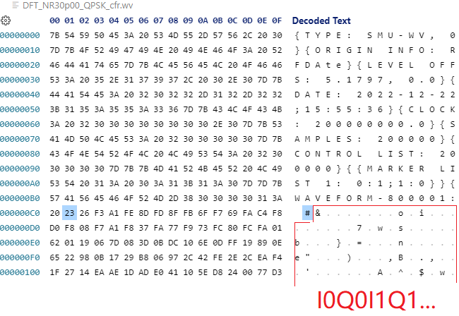
When importing file with *.wv extension, which is R&S *.wv format, sample rate and number of samples info will be read, so far only raw IQ data without encryption is supported. IQ format is 16-bit 2’s complement and little endian.
|
Voltage |
Dec |
Hex |
Endian Conv. |
|---|---|---|---|
|
+1.0 |
32767 |
0x7FFF |
FF7F |
|
0 |
0 |
0 |
0000 |
|
-1.0 |
-32767 |
0x8001 |
0180 |
If Waveform Type is Keysight Signal Studio, license information will be read out. Runtime Scaling, MarkerRoutingAlcHold, and MarkerRoutingPulse of the waveform will be read out and used as the default setting of hardware.
For other waveform types, there is no license information in selected waveform file. MarkerRoutingAlcHold and MarkerRoutingPulse of hardware will be none. Runtime Scaling of hardware will use default value.
Frequency offset adjustment is needed for carriers mixing only, resampling setting is put aside frequency offset because it will affect the minimal needed waveform sample rate. Carrier enable/disable can be set here too.
Calculate needed minimal sample rate of every carrier with formula
(fc + BW/2) *2*1.25, in which BW=original sample rate/1.25.
And named all result as (S1, S2, … Sn), then get maximal value as S_max, and name the original sample rate of corresponding carrier as S_ Original. then get needed minimal sample rate of combined signal with below formula:
V1=Math.ceil(S_max/ S_Original) * S_original
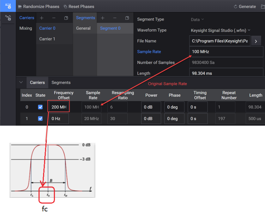
Figure 11 (above). Resampling ratio procedure when Sample Rate Mode is Auto.
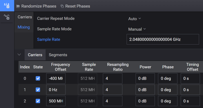
Find the least common multiple value from (S1, S2 …Sn) as V2
find minimal value from V1 and V2 as sample rate of waveform.
After the needed sample rate of waveform combination is got, the resampling ratio of every carrier can be calculated.
Sample rate of waveform
Resampling Ratio of every carrier
Normally important waveforms have different time lengths, after resampling operation on all carriers, sample length will vary from carrier to carrier. When combining waveforms, the user needs to decide which carrier will be repeated and which carrier will be truncated.
To describe the time alignment rule, here name all time length after frequency offset alignment is finished as T1, T2, … Tn.
Find the maximal value from T1, T2, … Tn and name it as T_max.
Firstly the (LCM) least common multiply value of T1, T2…Tn and name it as T_lcm.
If T_lcm ≤ 10* T_max, then repeat number of every carrier N_repeat=T_lcm/Tn, T_lcm will be the length of final combined waveform.
If T_lcm ≥ 10* T_max, then T_max will be the final length of combined waveform, which means the longest carrier which has maximal length of T_max will not be repeated.
For other carriers, N_repeat=Math. Round(T_max/Tn) +1;
You can change the repeat numbers of all carriers, then the maximal value will be found from T_n*N_repeat of all carriers. Then this value will be used as the final length of the combined waveform. Any waveform will be truncated after repeating.
Crest Factor Reduction enables the reduction of PAPR of the input waveform. With proper configuration, the PAPR of waveform can be suppressed to a specified level with certain damage. The peak cancellation algorithm is supported in AWU, which can be applied to any IQ waveform.
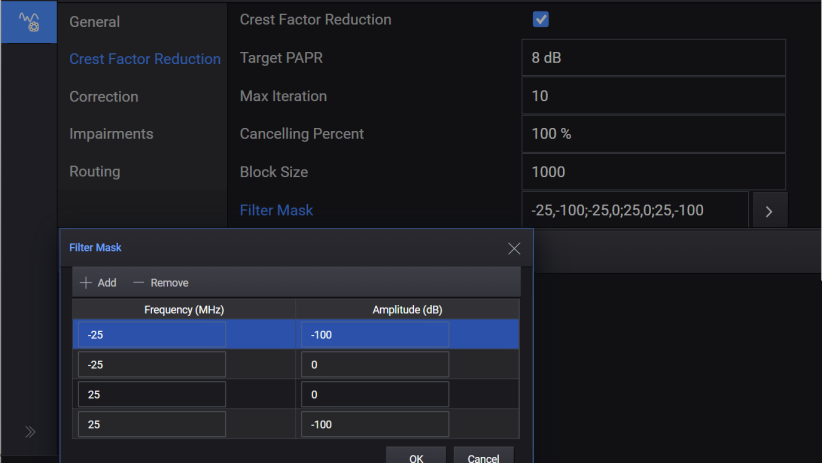
Figure 16 (above). Crest Factor Reduction.
|
Target PAPR |
Set the PAPR value to achieve after CFR. |
|
Max Iteration |
Specify the maximum times of iteration. With the increasing of iteration, the PAPR value should converge to a steady level. |
|
Cancelling Percent |
Specify the percentage that the cancellation pulses can be removed. |
|
Block Size |
Block is the range that a single cancellation pulse can be identified. If the waveform length is L, and the block size is B, then the number of blocks is N = floor(L/B) + 1. Therefore, there will be N pulses at most to be removed. |
|
Filter Mask |
A table is used to design a filter response in frequency domain. In the table, the frequency points are entered with an order of increasing frequency in unit of MHz, and its corresponding amplitude is in unit of dB. |
Apply correction is done by using correction data from one .csv file and then applying the correction on the waveform. Currently, only equalization is supported by applying reversion of channel response on the waveform. Apply correction can be enabled or disabled on GUI.
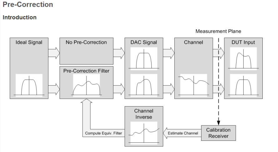
Figure 17 (above). Introduction to Pre-Correction.
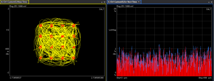
Figure 18 (above). Signal without correction applied.
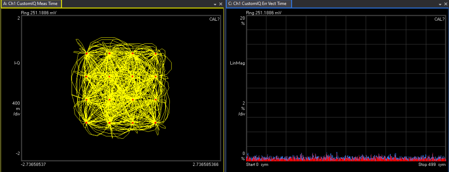
Figure 19 (above). Signal with correction applied.
Normally, a correction file is created by calibration of AWU. But a custom correction file can be used, with the following format requirements for custom correction file,
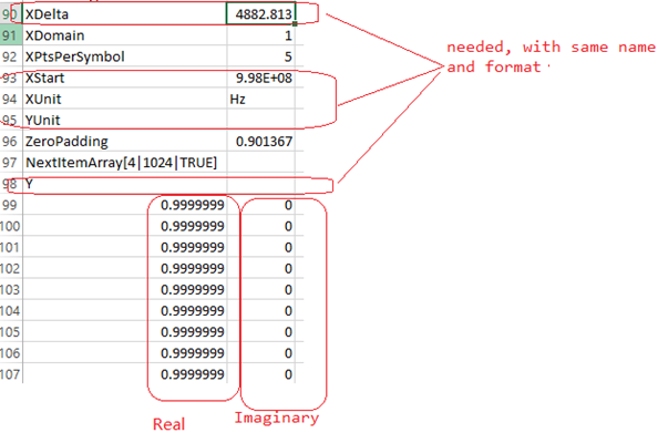
Figure 20 (above). Custom correction file with requirements.
Four types of waveform file (.wfm, .csv, .bin, . mat) can be imported and all waveform files will be exported to local disk as .wfm file before downloading into hardware.
If only one *. wfm file type is imported, license information of exported waveform will be same as imported waveform. Otherwise license information will be empty if other waveform file types are imported.
RMS value will always be calculated and written to waveform header for any waveform type.
Regarding RuntimeScaling , if only one selected waveform imported and it’s type is Keysight Signal Studio, then RuntimeScaling of selected waveform will be copied into exported waveform. Otherwise RuntimeScaling value will be copied from Hardware side into exported waveform.
The Export Data function is used to export the combined waveform in Keysight 16 Bin (*.bin) format to local disk. However, if the imported waveforms are Keysight Signal Studio format (*.wfm), then combined waveform cannot be exported. You can export waveform data as Big Endian, Little Endian, or .csv.
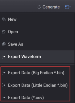
Figure 26 (above). Export Waveform.
This feature is used to embed some impairment into waveform. Currently, channel flatness is supported, which is used to apply user input filter.

User Flatness Profile is used to select the *.csv file which contains user-defined filter data, the content format needs to follow the below-mentioned convention.
YFormat,RI
XDelta,30000.0
XStart,-49140000.0
Y
0.707946,0.000000
0.707946,-0.000003
0.707948,-0.000008
0.707950,-0.000015
0.707953,-0.000026
0.707957,-0.000038
0.707962,-0.000054
0.707968,-0.000072
0.707975,-0.000092
0.707982,-0.000115
0.707991,-0.000141
0.708000,-0.000169
0.708011,-0.000200
0.708022,-0.000233
YFormat is used to define the meaning of data, may be RI, MA, or DB. GD
RI: Y data are real/ imaginary pairs.
MA: each pair represents absolute magnitude and angle in degrees.
DB: each pair represents magnitude in decibels and angle in degrees.
GD: each pair represents magnitude in decibels and time delay in seconds.
XDelta is the frequency step for all Y data pairs.
XStart is the start frequency which corresponds to first Y data pair,
Y is used to meaningful filter data will start in next line,
Filter data is defined as complex data array, so every line Y data has 2 columns, which is separated with one char which can be comma, semicolon, or space.
Click the following links to access a sample .csv file for User Flatness Profile. The two files are in RI and GD formats with same effects.